|
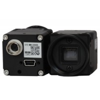
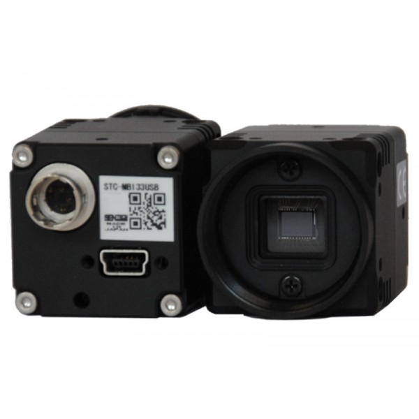
Camera Sensor
|
|
|
Image Sensor
|
1/1.8” Interline UXGA Color Progressive CCD: ICX274AQ (Sony)
|
|
Optical Format
|
1/3”
|
|
Pixel Size
|
4.4 x 4.4μm
|
|
Resolution
|
1688 x 1248
|
|
Camera Specifications
|
|
|
Frame Rate
|
15 fps
|
|
Bit Depth
|
8 bit
|
|
Gain
|
Manual and automatic control
|
|
White Balance
|
Manual and automatic control
|
|
Mechanical Specifications
|
|
|
Data Interface
|
USB 2.0
|
|
Lens Mount
|
C-Mount standard
|
|
Dimensions (L x W x H)
|
28mm x 28mm x 33.8mm
|
|
Mass
|
38g
|
|
Power and Emissions
|
|
|
Power Consumption
|
<450 mA
|
|
Power Requirement
|
USB bus power only
|
|
Emissions Compliances
|
FCC Class BE, CE Certified
|
|
Hazardous Materials
|
RoHS, WEEE Compliant
|

Quantum Efficiency Curve
|
Model
|
Type
|
Version
|
Mega Pixels
|
Resolution
|
Frame Rate (FPS)
|
Sensor
|
C" Mount
|
|
CC2100RC |
USB 2.0 | Color | 1.4MP | 1392 x 1040 | 15fps by USB 2.0 | 1/2" CCD | 0.5X |
|
CC2100M |
USB 2.0 | Monochrome | 1.4MP |
1392 x 1040 |
15fps by USB 2.0 | 1/2" CCD | 0.5X |
|
CC2200C |
USB 2.0 | Color | 2MP | 1616 x 1216 | 12fps by USB 2.0 | 1/1.8"CCD | 0.5X |
|
CC2200M |
USB 2.0 | Monochrome | 2MP |
1616 x 1216 |
12fps by USB 2.0 | 1/1.8"CCD | 0.5X |
|
CC2300C |
USB 2.0 | Color | 3.3MP |
2080 x 1536 |
5fps by USB 2.0 |
1/1.8"CCD |
0.5X |
|
CC5000C |
USB 2.0 | Color | 5MP |
2448 x 2048 |
9fps by USB 2.0 |
2/3"CCD |
0.7X |
|
CC5000M |
USB 2.0 | Monochrome | 5MP | 2448 x 2048 |
9fps by USB 2.0 |
2/3"CCD |
0.7X |
|
CC1400C |
USB 2.0 | Color | 1.4MP | 1392 x 1040 | 15fps by USB 2.0 | 2/3" Cooled CCD | 0.7X |
|
CC1400M |
USB 2.0 | Monochrome | 1.4MP | 1392 x 1040 | 15fps by USB 2.0 | 2/3" Cooled CCD | 0.7X |
|
CC1400UC |
USB 2.0 | Color | 1.4MP | 1392 x 1040 | 15fps by USB 2.0 | 2/3" CCD | 0.7X |
|
CC1400UM |
USB 2.0 | Monochrome | 1.4MP | 1392 x 1040 | 15fps by USB 2.0 | 2/3" CCD | 0.7X |
|
CC3200C |
USB 2.0 | Color | 2, 8, 16 & 32MP | 1616 x 1216 6464 x 4864 |
12fps by USB 2.0 (SXGA) |
1/1.8" CCD | 0.5X |
|
ST3000C |
USB 2.0 | Color | 2MP | 1688 x 1248 | 15fps by USB 2.0 | 1/1.8" CCD | 0.5X |
CCD vs CMOS
Meiji Techno America allows Digital / Analog CCD and CMOS cameras to be mounted directly to a microscopes trinocular port using the proper C” mount adapter that match’s the chip size of the camera. Any digital or video camera with a “C” mount ( 1” diameter thread) can be mounted on any Meiji Techno Trinocular microscope ( 25.2 tube ) by using these “ C”- mount attachments. They are available with projection lenses of different powers allowing some control over the magnification and the field view. “CS” mount cameras with require part number V-5MM to be threaded on prior to installing the adapter. Meiji Techno America’s adapters depend on the quality of our Japanese lenses. Our microscope adapters are designed and developed individually for each camera’s lens system and therefore it effectively eliminates vignetting and minimizes optical errors often associated with photomicrography by a consumer digital /analog camera. The image quality, peripheral resolution and color rendering is optimum as you would expect for a high quality Japanese C” mount adapter from Meiji Techno.
Generally low end adapters in the market have one or more of the following problems often associated with photomicrography:
Introduction to Image Sensors
Since every Digital camera has a sensor, it is usually either a CCD or a CMOS type chip sensor. All sensors are analog devices, converting photons into electrical signals. The process by which the analog information is changed to digital is called Analog to Digital conversion. When an image is being captured by a network camera, light passes through the lens and falls on the image sensor. The image sensor consists of picture elements, also called pixels, that register the amount of light that falls on them. They convert the received amount of light into a corresponding number of electrons. The stronger the light, the more electrons are generated. The electrons are converted into voltage and then transformed into numbers by means of an A/D-converter. The signal constituted by the numbers is processed by electronic circuits inside the camera. Presently, there are two main technologies that can be used for the image sensor in a camera, i.e. CCD(Charge-coupled Device) and CMOS (Complementary Metal-oxide Semiconductor). Their design and different strengths and weaknesses will be explained in the following sections.
Color Filtering
Image sensors register the amount of light from bright to dark with no color information. Since CMOS and CCD image sensors are ‘color blind’, a filter in front of the sensor allows the sensor to assign color tones to each pixel. Two common color registration methods are RGB (Red, Green, and Blue) and CMYG (Cyan, Magenta, Yellow, and Green). Red, green, and blue are the primary colors that, mixed in different combinations, can produce most of the colors visible to the human eye.
CCD Technology
In a CCD sensor, the light (charge) that falls on the pixels of the sensor is transferred from the chip through one output node, or only a few output nodes. The charges are converted to voltage levels, buffered, and sent out as an analog signal. This signal is then amplified and converted to numbers using an A/D-converter outside the sensor. The CCD technology was developed specifically to be used in cameras, and CCD sensors have been used for more than 30 years. Traditionally, CCD sensors have had some advantages compared to CMOS sensors, such as better light sensitivity and less noise. In recent years, however, these differences have disappeared. The disadvantages of CCD sensors are that they are analog components that require more electronic circuitry outside the sensor, they are more expensive to produce, and can consume up to 100 times more power than CMOS sensors. The increased power consumption can lead to heat issues in the camera, which not only impacts image quality negatively, but also increases the cost and environmental impact of the product. CCD sensors also require a higher data rate, since everything has to go through just one output amplifier, or a few output amplifiers.
CMOS Technology
Early on, ordinary CMOS chips were used for imaging purposes, but the image quality was poor due to their inferior light sensitivity. Modern CMOS sensors use a more specialized technology and the quality and light sensitivity of the sensors have rapidly increased in recent years. CMOS chips have several advantages. Unlike the CCD sensor, the CMOS chip incorporates amplifiers and A/D-converters, which lowers the cost for cameras since it contains all the logics needed to produce an image. Every CMOS pixel contains conversion electronics. Compared to CCD sensors, CMOS sensors have better integration possibilities and more functions. However, this addition of circuitry inside the chip can lead to a risk of more structured noise, such as stripes and other patterns. CMOS sensors also have a faster readout, lower power consumption, higher noise immunity, and a smaller system size. It is possible to read individual pixels from a CMOS sensor, which allows ‘windowing’, which implies that parts of the sensor area can be read out, instead of the entire sensor area at once. This way a higherframe rate can be delivered from a limited part of the sensor, and digital PTZ (pan/tilt/zoom) functions can be used. It is also possible to achieve multi-view streaming, which allows several cropped view areas to be streamed simultaneously from the sensor, simulating several ‘virtual cameras’.
Main Differences
A CMOS sensor incorporates amplifiers, A/D-converters and often circuitry for additional processing, whereas in a camera with a CCD sensor, many signal processing functions are performed outside the sensor. CMOS sensors have a lower power consumption than CCD image sensors, which means that the temperature inside the camera can be kept lower. Heat issues with CCD sensors can increase interference, but on the other hand, CMOS sensors can suffer more from structured noise. A CMOS sensor allows ‘windowing’ and multi-view streaming, which cannot be performed with a CCD sensor. A CCD sensor generally has one charge-to-voltage converter per sensor, whereas a CMOS sensor has one per pixel. The faster readout from a CMOS sensor makes it easier to use for multi-megapixel cameras. Recent technology advancements have eradicated the difference in light sensitivity between a CCD and CMOS sensor at a given price point.
Conclusion
CCD and CMOS sensors have different advantages, but the technology is evolving rapidly and the situation changes constantly. Using the proper C” mount adapter from Meiji Techno America will maximize your image quality that you are seeing through your microscope lens.
Note: Reduction lenses (i.e. magnification factors less than 1.0x) are commonly used to compensate for the increased magnification factor inherent with cameras used on microscopes.